
Butterfly Valve Lockout: Handle Fit and Isolation Checks
A butterfly valve lockout is selected by the valve’s operating mechanism, handle geometry and available locking space. First determine whether the valve uses a squeeze lever, pull handle, handwheel or actuator. Then match a documented lockout design to that exact arrangement and verify the complete assembly with the intended personal padlock. Pipe diameter alone cannot establish fit. Locking a handle also does not demonstrate that the valve is leak-tight or that trapped pressure has been removed; those questions require the equipment-specific isolation procedure.
This guide focuses on selecting a device for manually operated butterfly valves. It complements the separate guides to gate valve lockout sizing and ball valve lockout selection, whose mechanisms should not be assumed interchangeable with a butterfly-valve lever.
Identify the operating mechanism before measuring
Photograph the valve’s nameplate and the complete operator from safe accessible positions. Include the lever, trigger, quadrant plate and surrounding pipework where present. A long lever with a squeeze trigger presents a different problem from a handwheel on a gearbox. An actuator brings additional energy-control questions that a manual-handle cover may not address at all.
Have the responsible process specialist identify the correct valve and required isolation position. A visually similar valve on an adjacent line can serve a different duty. The device assessment should therefore reference the equipment or isolation-point identifier, rather than a photograph labelled only “red valve.” Confirm the manufacturer’s instructions before selecting an attachment location.
Do not remove a handle, defeat a trigger or modify the operator to make an accessory fit. Changes to a valve assembly can affect operation and introduce unassessed hazards. If the operator cannot be matched to a documented device application, retain an unresolved status and request an alternative engineered arrangement through the site’s approval process.
Understand what a lever lockout must restrain
A squeeze-lever operator commonly involves both a lever and a release trigger. A candidate lockout must prevent the movements required to operate the valve, within the exact design’s instructions. Merely covering the end of a handle may leave a release accessible or permit enough travel to change valve position.
Assess how the selected device engages the existing operator. Check whether the body can slide off, lift free or rotate away once locked. Conduct only the approved fitting checks, on equipment made safe for that assessment. There is no universal hand force or improvised impact test suitable for every valve and plastic lockout.
Keep the fitting assessment separate from a process isolation test. The CCOHS hazardous energy guidance describes energy control as a wider system of procedures and controls. A correctly restrained operator is useful evidence about hardware engagement, but not proof that downstream work is safe to start.
Build a measurement record around the handle
Measure the features identified in the candidate device’s drawing. These may include the rod or handle cross-section, trigger clearance, required engagement length and space around the operator. Record exactly where each measurement was taken. A rounded handle can have substantially different dimensions at its grip and its pivot.
Also document obstructions. Flanges, insulation, guards and neighboring valves may prevent a sliding cover from reaching its intended position. A handle can fall within a listed size range while its surrounding installation makes the accessory unsuitable. Include a side view and the intended locked position in the review record, without moving equipment outside an authorized procedure.
Use a sample whenever the geometry is ambiguous. A dimensional sketch is valuable for screening, but a sample review can reveal interference between the lock body and the valve, or an exposed trigger that was not apparent from one photograph. Record the outcome against the exact product variant rather than the generic term “butterfly lock.”
| Operating arrangement | Evidence needed | Selection boundary |
|---|---|---|
| Squeeze lever | Handle profile, trigger travel and engagement area | Device must restrain the required operating movements |
| Pull handle | Full handle shape and intended cover method | Squeeze-trigger instructions cannot be assumed to apply |
| Gear operator | Handwheel, gearbox and approved locking provision | Assess the gearbox arrangement as a separate application |
| Actuated valve | Actuator type, supplies and stored energy | A manual lever cover alone is insufficient evidence |
| Congested installation | Side views and surrounding clearances | Confirm full installation and padlock closure are possible |
This is a qualitative selection checklist. The process-control basis remains the site’s assessed procedure and the CCOHS lockout guidance, rather than a claim that every operator in a row shares one lockout size.
Use the BOYUE BUV-01 information carefully
The BOYUE BUV-01 product page describes a polypropylene butterfly-valve lockout and lists a valve rod range of 8–45 mm and a padlock shackle diameter of no more than 7 mm. These are the stated screening dimensions for that listing; they are not a compatibility certificate for every handle within the range.
Ask BOYUE to confirm the exact measurement location, current drawing and fitting instructions for the supplied variant. The sample must match the quotation and the visible product configuration. Do not transfer capacities from a similarly coloured device sold by another manufacturer. Similar external form does not establish identical material, mechanism or operating limits.
Keep evidence about fit separate from evidence about environmental suitability. Ask for documented suitability for the expected exposure, cleaning process and duration. Avoid describing the lockout as universally chemical resistant or suitable for every outdoor location without the relevant product documentation and site review.
Consider cable alternatives only as approved assemblies
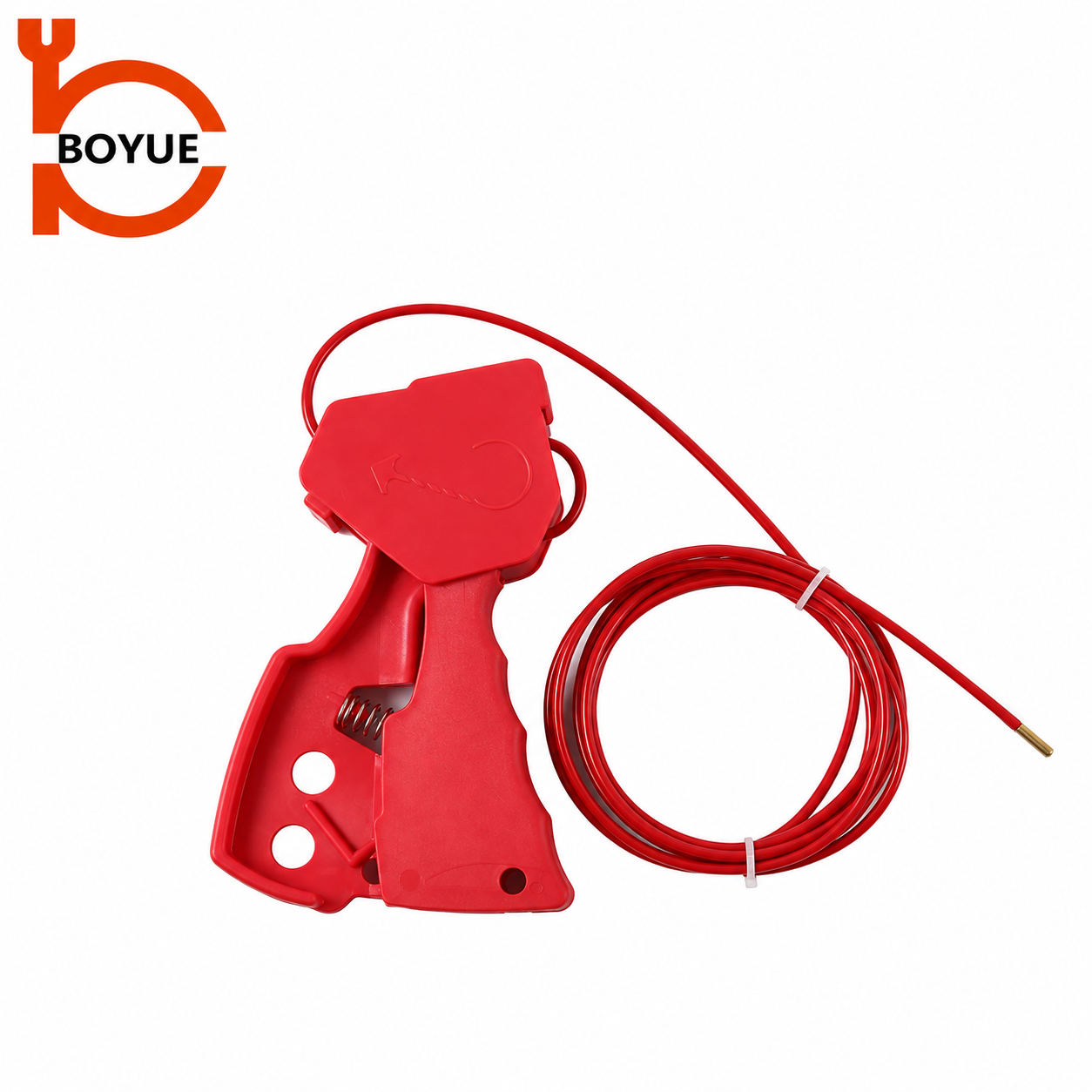
Some butterfly-valve applications use a cable-based or universal lockout arrangement. These require their own application instructions, cable route and anchoring assessment. A cable passed through any convenient opening does not automatically prevent operation. Slack, movement of the anchor point or access to the release mechanism can defeat the intended restraint.
Where a cable alternative is considered, document the exact device, cable and routing configuration. Confirm that the route cannot slip off the operator or allow the handle to move into an unsafe position. Do not infer that a flexible cable is a universal answer to every unusual handle. The separate cable lockout selection guide addresses the purchasing questions for that product family.
Do not improvise a combined assembly by mixing different devices because they appear to connect. Approval should cover the complete arrangement, including the personal lock and any hasp. If the supplier cannot document an intended application, escalate the fit problem rather than issuing instructions based on an untested photograph.
Verify the padlock and identification arrangement
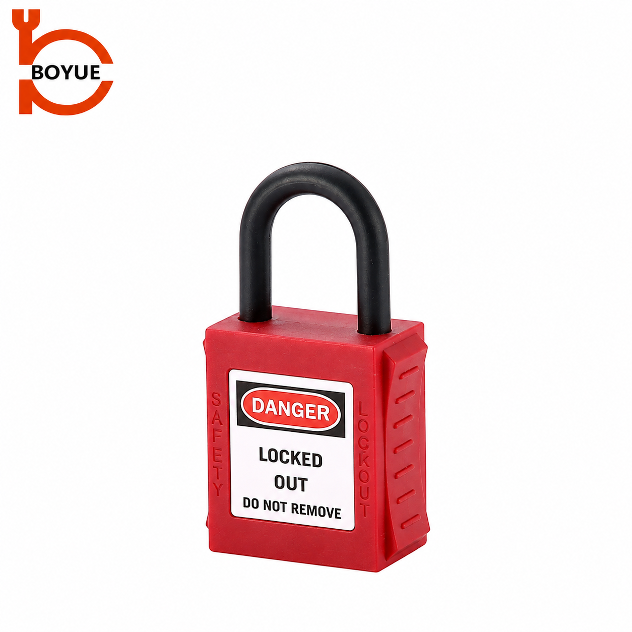
Check shackle diameter, internal opening and lock-body clearance together. A shackle may pass through a locking hole but leave insufficient room to close the lock without twisting the device. Review the final assembly with the site’s actual approved lock, not a convenient display lock with different dimensions.
For several workers, define the approved group arrangement before buying additional hardware. The number of visible holes on a product does not by itself establish a complete group-protection procedure. Confirm identification, key custody, handover and removal rules. A purchasing checklist should flag those unresolved questions rather than interpreting hole count as proof of suitability.
Position identification so it remains readable and does not interfere with the restraint mechanism. A photograph of the accepted sample can help receiving staff compare later deliveries. Retain the equipment identifier and fitted model with the record, so a replacement valve or changed operator triggers a fresh review.
Address trapped pressure and valve leakage separately
A closed valve can leave pressure or hazardous material trapped downstream. Its ability to provide the required isolation depends on the process, valve condition and work scope. Tasks involving line opening or hazardous substances may require additional isolation measures defined by the responsible specialist. A lockout cover is not a pressure boundary and does not repair a leaking valve.
The applicable energy-control requirements and written procedure must address residual and potentially reaccumulating energy. NIOSH’s hazardous energy control overview reinforces the need for a planned programme. Do not substitute a locked-handle photograph for the procedure’s verification record.
The educational video below explains general lockout principles. It is useful context for why a device belongs within an organized system, but it is not a BUV-01 installation demonstration or a process-isolation design guide.
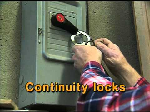
Watch Lock Out Procedures by SAFE Work Manitoba.
Create an enquiry and receiving checklist
Provide the valve and operator references, equipment identifier, measured handle geometry, safe photographs, expected environment and proposed lock dimensions. Request the exact device model, instructions, included parts and any application exclusions. Distinguish a device-only order from an order including locks or accessories.
On receipt, compare the delivered mechanism and labels with the approved sample. Inspect for cracks, damaged locking features and missing parts. Keep unassessed substitutions out of active stock. Recheck compatibility after a valve, actuator, handle or surrounding installation changes, even when the original product remains in serviceable condition.
Compare the broader BOYUE valve lockout range when identifying an operator family; choose the final device through the documented application assessment.
Frequently asked questions
Can butterfly-valve pipe size determine lockout size?
No. Operator geometry and the selected device’s engagement method determine fit. Pipe size can identify the valve family but does not replace handle measurements and a complete fitting assessment.
Does a locked butterfly valve prove zero pressure downstream?
No. Trapped pressure, leakage and other energy sources require separate assessment and verification under the equipment-specific procedure.
Can a ball-valve device be used on a butterfly lever?
Only if the exact device instructions and the site assessment approve that application. Similar lever appearance is insufficient evidence.
What is the most useful sample record?
Record the valve and operator references, isolation-point identifier, device model, actual personal lock, installation photographs, fitting outcome and any limits on where that approved arrangement may be used.