
Emergency Stop Button Lockout: Limits and Selection Checks
An emergency stop button lockout can restrict access to a compatible control or prevent an unauthorized reset, depending on its documented design. It does not turn a control-circuit button into an energy-isolating device. Before selecting a cover, establish its permitted role in the machine’s assessed safety arrangements, confirm that required emergency access is preserved, and verify the exact button and cover geometry. For maintenance involving hazardous energy, identify and secure the actual isolation points and complete the required verification under the equipment-specific procedure.
This article addresses the boundary between control access and energy isolation, plus the purchasing checks for a button cover. The existing switch lockout introduction provides broader context. A catalogue name containing “lockout” does not by itself establish the legal or technical function of the control underneath it.
Distinguish stopping from isolating
A stop command changes the state of a machine control system. An energy-isolating device physically prevents the transmission or release of energy within the relevant definition. These functions can involve different components and different failure modes. A machine that has stopped can still contain electrical supplies, pressure, stored mechanical energy or other hazards.
OSHA 29 CFR 1910.147 expressly excludes push buttons, selector switches and other control-circuit devices from its definition of energy-isolating devices. That US general-industry rule has a defined scope; other tasks and jurisdictions need their applicable requirements. The distinction is still essential when reading a supplier’s product name or an enquiry description.
Do not assume that preventing reset provides the same protection as isolating the supply. It may serve a separately assessed control-access purpose, but the machine’s safety design and maintenance procedure must determine that role. A plastic cover has no independent knowledge of which energy sources remain present or whether the control system can fail.
Establish whether a cover is appropriate at all
Before measuring a button, ask the machine’s responsible safety specialist whether an accessory cover is permitted in the intended operating condition. Required emergency-stop access must remain available wherever the machine design and applicable requirements demand it. Do not install a lockable obstruction over an active emergency control simply to prevent nuisance operation.
Describe the intended condition precisely: for example, access restriction during an assessed shutdown state, rather than an unrestricted claim of “safer operation.” The review should consider who can apply and remove the cover, what prevents unexpected changes in machine state and how affected personnel will understand its purpose.
If the intended use conflicts with required emergency access, stop the product-selection exercise and resolve the machine-safety requirement. Choosing a larger cover or a different colour cannot solve an unsuitable use case. A purchasing department should retain that decision boundary in the enquiry instead of treating every button-cover request as an ordinary dimensional match.
Record button shape and reset movement
Identify the button manufacturer and full reference, mounting arrangement, head dimensions and protrusion above the panel. Include any surrounding collar or guard. Record whether reset involves rotation, pulling or another mechanism, using the manufacturer’s information. Two buttons with the same nominal mounting size can have different heads and reset envelopes.
A cover must accommodate the actual geometry without unintentionally pressing, pulling or rotating the button. The space required to operate a hinged cover may exceed its closed footprint. Nearby indicators, labels and neighboring controls can create interference even where the button itself fits within the internal cavity.
Take measurements under authorized safe conditions. Do not remove a panel or dismantle the emergency-stop assembly to produce a sales photograph. If the drawing does not identify which dimensions control fit, ask the cover supplier for clarification. An unexplained “diameter” in a catalogue is insufficient for a rectangular guard or a projecting reset mechanism.
| Review area | Evidence needed | Reason to withhold approval |
|---|---|---|
| Intended role | Written machine-safety decision and permitted state | Cover would block required emergency access |
| Button envelope | Head size, protrusion and reset movement | Cover touches or changes the control state |
| Mounting | Exact fixing method and panel layout | Installation requires unapproved machine modification |
| Hinged movement | Open and closed clearances | Cover fouls another control or cannot close completely |
| Personal lock | Shackle dimensions and lock-body space | Lock cannot secure the intended feature |
| Energy isolation | Named isolating devices and verification method | Button cover is being treated as sole isolation |
This is an application-screening table, not a machine-safety validation checklist. The distinction between circuit controls and isolation is also explained in CCOHS’s lockout guidance.
Confirm the exact BOYUE product variant
The BOYUE WSL-03 product page describes a transparent PC cover that restricts access to a switch or control. The illustration shows the product by itself. It does not demonstrate an approved installation on every emergency-stop or wall-switch assembly.
Ask BOYUE for a current drawing, fitting method, instructions and exclusions for the exact variant supplied. Confirm the internal usable space, rather than relying only on external size. Resolve how the base attaches and whether the proposed method is acceptable to the machine manufacturer and responsible site reviewer.
Do not add unsupported electrical, impact, ingress-protection or safety-integrity claims to the purchase specification. Transparent material lets a user see through a cover; it does not prove that an enclosed control is electrically isolated or that a safety function has been validated. Those are separate technical questions requiring their own evidence.
Identify the actual isolation hardware separately
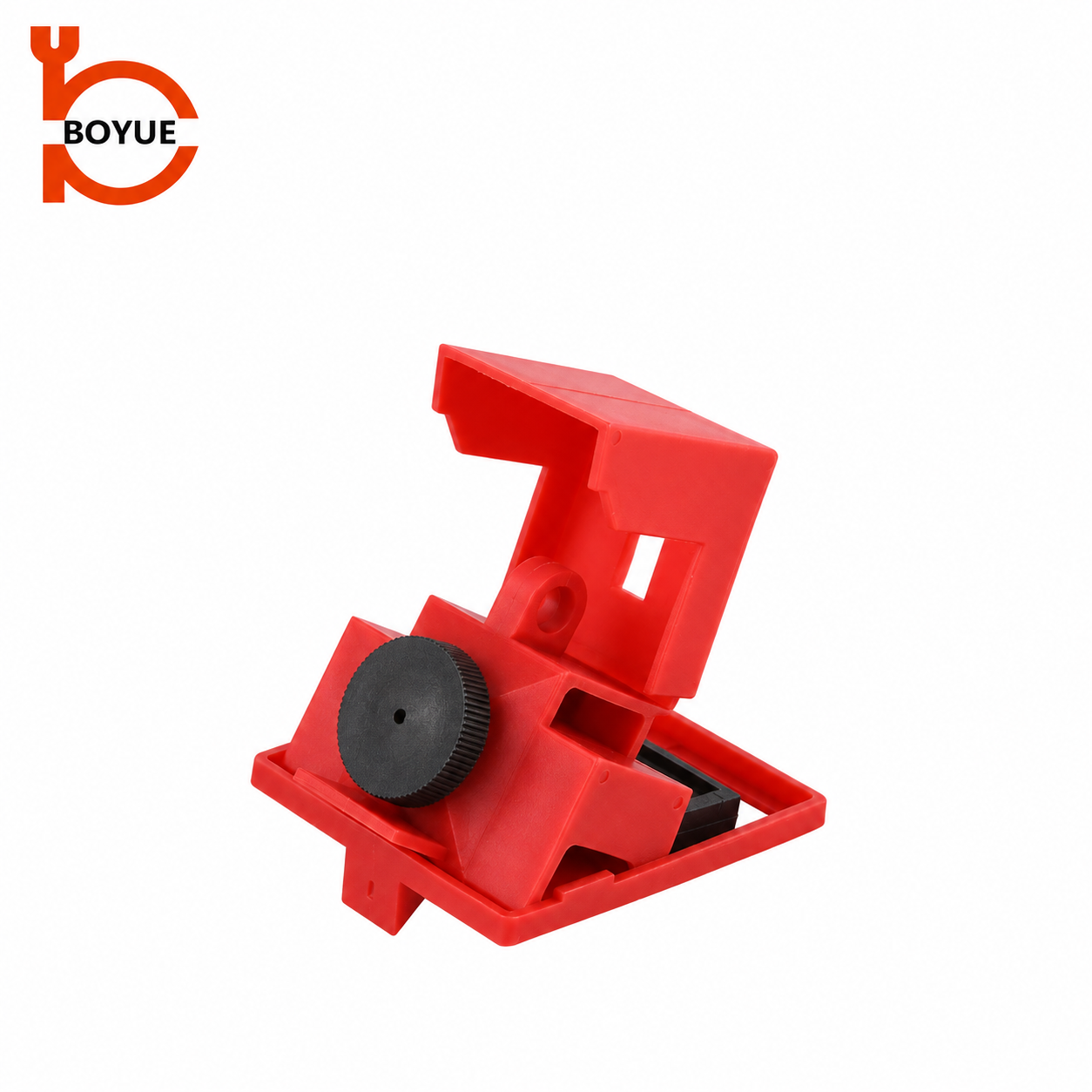
When hazardous-energy isolation is required, the procedure should identify the appropriate disconnects, breakers, valves or other approved isolating devices. A breaker lockout, shown separately above, illustrates a different hardware category. Its suitability still depends on the breaker and installation; it is not a universal alternative that can be chosen from a photograph.
The clamp-on breaker fit guide addresses that interface assessment. If electrical work is involved, OSHA’s electrical work practices have their own relevant provisions. The correct procedure and qualified-person responsibilities must be established for the actual task.
A stopped machine may have more than one supply and may retain stored energy. Identify those hazards rather than making a one-for-one substitution between a button cover and a breaker clamp. The task assessment determines the full combination of controls, verification and responsibilities needed before work begins.
Verify the cover and padlock as one assembly
Once the application has been approved, conduct the specified fitting assessment with the actual lock. Check that the cover closes without pressure on the control, that the locking feature engages and that the cover cannot be displaced in the ways the instructions require it to prevent. Do not invent a torque or pulling-force test.
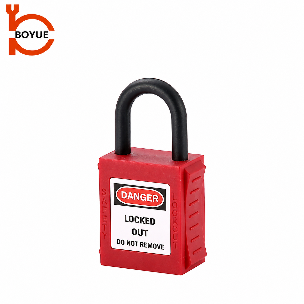
Check shackle diameter, usable height, internal width and body clearance. A lock can fit through a hole while preventing the cover from sitting correctly. Record the exact lock model and configuration with the accepted assembly so receiving staff can detect a substitution. The padlock image below illustrates a separate component, not proof of installed compatibility.
Keep identification clear about the purpose of the cover. A label should not suggest that all energy is isolated when the device is only restricting control access. Use wording approved under the site’s programme, preserving any required manufacturer warning and avoiding ambiguous terms that could mislead a worker arriving later.
Control issue, removal and changes
Define who may issue the cover and which equipment applications are approved. Store unassessed variants separately. A generic drawer labelled “electrical locks” can invite a button cover to be used where a breaker or plug device is required. Distinguish the product categories and their application limits in the issue record.
Removal must follow the approved responsibility and machine-state arrangements. Do not reset the button, energize the machine or remove someone else’s personal lock merely because an enclosure appears ready. The written procedure must address communication, clearance of personnel and any further verification required for returning the equipment to service.
Review the application after changes to the button, panel, control system, cover model, mounting method or intended operating state. An unchanged external appearance does not prove an unchanged safety function. Retain the original approval record so the reviewer can identify what evidence needs to be repeated.
Prepare an enquiry that states the boundary
Send the button reference, photographs, dimensions, surrounding clearances and permitted cover purpose. Ask for the exact model, materials, fixing method, current instructions and contents of supply. State explicitly that a control cover is not being accepted as the sole hazardous-energy isolation measure for maintenance.
On receipt, compare the supplied base, hinge, locking features and clear body with the accepted sample. Reject cracks, missing parts or unexplained design changes. Confirm any required mounting review before installation. Do not allow urgent delivery needs to turn a preliminary dimensional match into an approval of the machine’s safety arrangement.
The SAFE Work Manitoba video below provides general lockout education. Its purpose here is to reinforce the need for defined isolation procedures, not to demonstrate WSL-03 installation or approve covering a particular emergency-stop control.
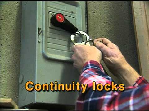
Watch Lock Out Procedures by SAFE Work Manitoba.
For cord-connected equipment, the electrical plug lockout sizing guide addresses another distinct interface. Its scope and the applicable procedure must be assessed independently of a button cover.
Frequently asked questions
Does locking an emergency-stop button isolate the machine?
A control-circuit button is not an energy-isolating device under OSHA’s cited definition. Identify and secure the actual isolation points and control stored energy under the applicable procedure.
Can a cover be installed over every emergency stop?
No. Its intended role, required emergency access, machine design, mounting and geometry must be assessed before use. A dimensional fit alone is insufficient.
Is a transparent cover proof of electrical protection?
No. Transparency describes visibility through the material. Electrical protection and isolation require separate documented evidence and appropriate procedures.
What should be checked after a button is replaced?
Reassess the button reference, geometry, reset movement, cover engagement, mounting, neighboring controls and permitted use. Confirm the complete assembly remains within its approved application.