Pneumatic Lockout and Stored Energy: Residual Pressure Checks
Pneumatic lockout stored energy control requires more than stopping the air supply or preventing a hose from being reconnected. Compressed air can remain trapped downstream, and releasing pressure can also allow an unsupported part to move. Authorized personnel must follow the equipment-specific procedure to identify every relevant energy source, isolate it, control residual energy and verify the safe condition before work. A quick-disconnect lockout helps prevent reconnection in an approved arrangement; it does not vent a cylinder, measure pressure or prove that the whole machine has been de-energized.
Define the work boundary before choosing a device
Start with the task, equipment identification and current drawings or manufacturer information. Identify what is being serviced and which movements or releases could expose people. A portable air tool, a cylinder-driven fixture and a machine with several pneumatic zones can require different control arrangements even when their supply connectors look similar.
Ask whether there are alternative air feeds, branch lines, receivers, trapped sections or components that maintain force after the supply is isolated. Check for related electrical, mechanical and gravitational hazards as well. A pneumatic component can be part of a machine whose most dangerous remaining movement comes from a spring or suspended load.
The site’s pneumatic quick-disconnect lockout selection guide addresses connector fit. Use the present guide to understand the residual-energy questions that selection alone cannot answer. Do not use a general article to invent a machine-specific shutdown sequence or select an unverified vent point.
Understand what the lockout physically prevents
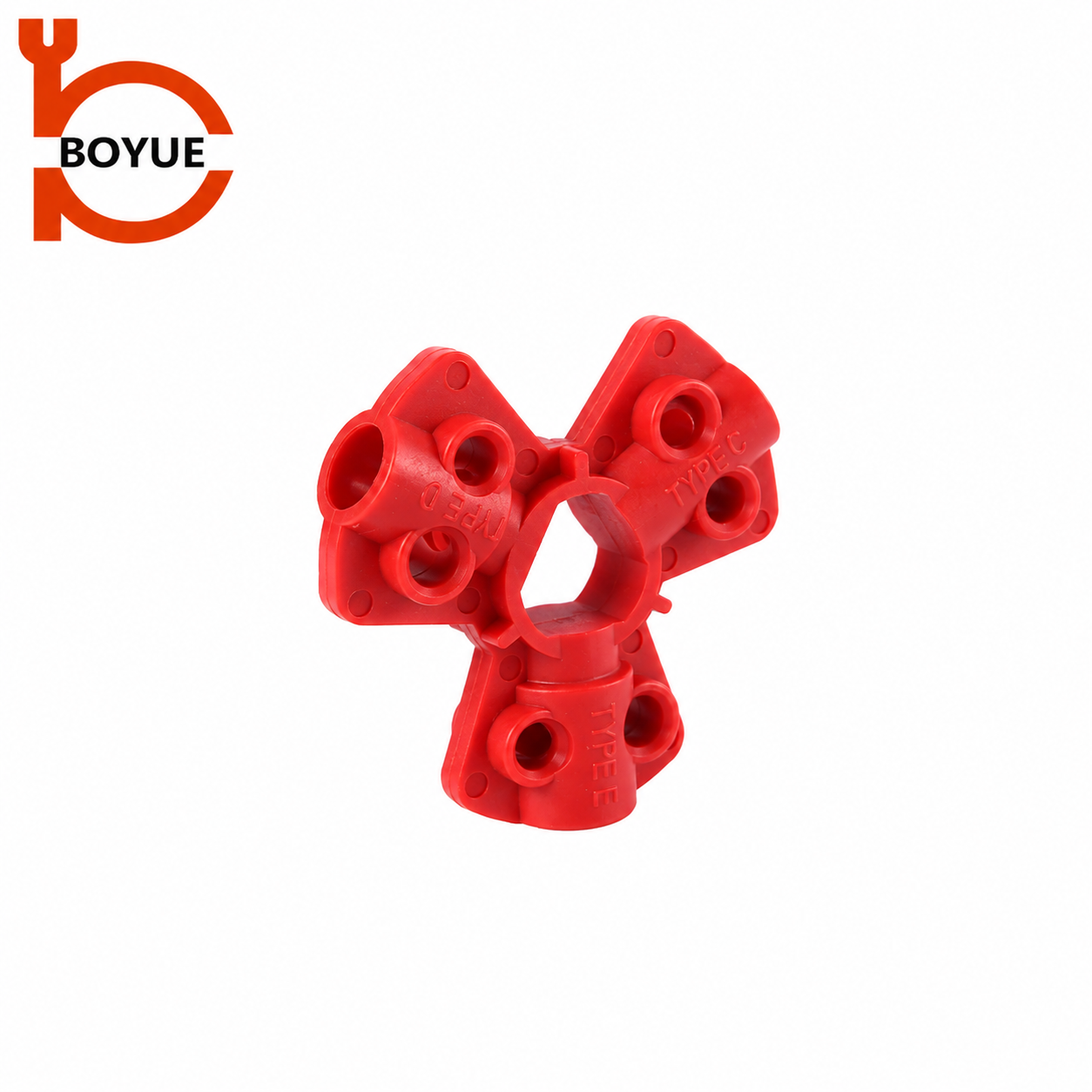
The BOYUE AS-01 pneumatic quick-disconnect lockout is a physical device associated with a disconnected air fitting. Its appropriate role must be confirmed for the exact connector and approved application. The product photograph is not a diagram of a complete energy-control system.
Check the actual fitting profile, retention geometry and compatible personal padlock. The connection must remain prevented in the intended locked arrangement. Do not assume that a device fitting loosely around a hose prevents reconnection, and do not improvise a way to connect or disconnect equipment under pressure. Carry out any fit demonstration only in a safely unloaded, approved situation.
A connector lockout does not automatically provide a locked-open exhaust path or control another supply branch. Where the procedure requires a lockable isolation and exhaust valve, evaluate that function separately with the responsible technical personnel. A reconnection-prevention device and a pressure-control component serve different purposes even if both appear in the same equipment procedure.
Locate trapped energy and movement caused by depressurization
Residual pressure may remain in a cylinder chamber, hose section or other volume isolated by the system’s internal components. The exact locations depend on the design. A drawing and an equipment-specific assessment are more reliable than assuming air always drains back through the main supply connection.
CCOHS’s hazardous energy guidance explains that isolating an incoming source does not by itself remove residual energy. Treat that distinction as a planning question for each work zone: what can still exert force, and how will the approved procedure make that condition safe?
Pressure removal may itself change the mechanical state. A part supported by pneumatic force may lower, rotate or release a clamped item when that force disappears. Do not enter its movement path while attempting to confirm depressurization. Determine the required mechanical support or restraint before any release, following the equipment design and approved instructions.
Avoid replacing this assessment with a timed wait. Exhaust time depends on the actual system and is not established by the connector lockout’s appearance. A fixed delay copied from another machine cannot show whether a blocked path or isolated chamber still contains hazardous pressure.
Make verification specific to the hazard
Verification should establish the safe condition relevant to the planned work. The procedure needs to state what is checked, where it is checked, who is authorized and what result permits the task to proceed. A gauge or other indicator must be appropriate to the relevant zone and used according to the applicable instructions.
A zero reading at one location is not universal evidence about every trapped section. Likewise, a machine that does not respond to a normal control may still retain hazardous force. Use the verification methods specified for the equipment; do not improvise by loosening fittings, cracking lines, removing a guard or entering a danger zone to see what happens.
OSHA 1910.147(d)(5)–(6) addresses stored energy, continued verification where hazardous reaccumulation is possible and verification before covered work begins. Translate those requirements into the employer’s equipment-specific process. No universal test pressure, waiting period or monitoring interval is established here.
Record the unanswered questions before work starts
This qualitative table is a planning and handover aid. It follows the isolation-versus-residual-energy distinction described by CCOHS and OSHA; it is not an operating sequence or permission to perform pressure work.
| Question | Evidence the procedure should identify | If unresolved |
|---|---|---|
| Where can air enter? | Each relevant supply, branch and alternate source | Stop planning release until the boundary is known |
| What prevents reconnection? | Approved isolating and locking arrangement | Resolve connector/device compatibility |
| Where can pressure remain? | Relevant trapped sections and safe release provisions | Obtain equipment-specific technical guidance |
| What moves when pressure falls? | Loads, clamps, springs and required restraints | Establish approved support before release |
| How is the safe condition verified? | Specified check locations, methods and acceptance result | Do not substitute silence or elapsed time |
| Can energy return? | Reaccumulation assessment and continued verification requirements | Maintain protection and resolve the cause |
| Who owns each action? | Authorized persons and handover responsibility | Resolve accountability before maintenance |
Use the record to identify a missing procedure step, rather than writing a vague instruction such as “check air is off.” A useful question names the equipment zone and the hazard it addresses. Keep technical assessment records available to the people applying the procedure so the next shift does not have to infer the intended boundary.
Treat reaccumulation as a separate condition
Initial verification is a point in the work process. If hazardous energy can build again, the procedure must address that possibility throughout the relevant period. An isolation point that leaks, an alternate feed or a changed system configuration may require technical investigation; this article does not diagnose the cause from a gauge trend.
If pressure or unexpected movement reappears, stop the task and follow the site’s safe response and escalation process. Do not continue maintenance while someone periodically vents an unexplained pressure rise as an informal workaround. Maintain personnel protection while the responsible team determines how to establish an effective boundary.
Record the observed condition, time, affected zone and personnel notified. Preserve the distinction between an instrument fault, an incomplete isolation and a system design issue until competent personnel assess the evidence. Replacing the plastic connector lockout cannot be assumed to correct pressure entering by another route.
Maintain personal protection through group work and shift changes
A single disconnected hose can serve equipment worked on by several people. The energy-control arrangement must protect everyone exposed, not merely the person who first installed the fitting lockout. Define how each authorized employee joins, verifies and leaves the job under the applicable site process.
The group lockout box procedure guide provides complementary context for accountability. A group box manages the agreed locking arrangement; it does not remove stored air or identify a missed isolation point. Keep the physical energy controls and the personnel record consistent when the job expands or another trade arrives.
Shift transfer also needs a planned handover. State the equipment condition, isolation boundary, remaining hazards, ongoing verification and who currently holds responsibility. Do not remove an outgoing employee’s lock simply because an incoming worker has arrived with a similar-looking one. Follow the employer’s approved transfer and removal rules.
Prepare a product enquiry without overstating the device’s role
For a pneumatic lockout enquiry, provide the fitting manufacturer’s identity where available, a safe photograph, relevant connector dimensions and the intended locking arrangement. State the padlock requirements and expected environment. Identify whether the request concerns AS-01, the separate AS-02 design or an application that still needs review.
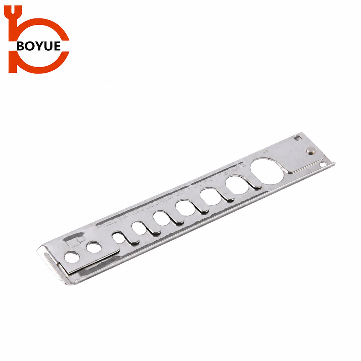
The visible shapes in the product photographs should remain distinct. A metal multi-aperture device is not proof that every aperture fits every coupling; a red multi-lobed device is not an exhaust valve. Ask for the exact variant and instructions rather than inferring pressure rating or complete-system suitability from material or appearance.
Also state what the product is expected to prevent. “Prevent reconnection of this identified disconnected fitting” is a reviewable purpose. “Make the machine safe” leaves unresolved isolation, residual energy, restraint and verification duties that a supplier photograph cannot answer. Keep those duties in the site’s technical and safety process.
Use general training alongside the actual procedure
The following SAFE Work Manitoba video explains general lockout principles. It is relevant to planning and verifying hazardous-energy control, but it does not demonstrate an approved pneumatic venting arrangement for your equipment. Product fit, pressure release and any mechanical restraint still require their own instructions and training.
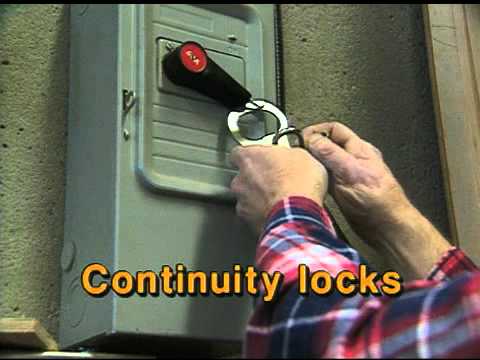
Watch Lock Out Procedures by SAFE Work Manitoba.
For a separate cylinder-supply application, see the gas cylinder lockout selection guide. A valve-access cover has a different physical role from an air-fitting device, and neither establishes that a connected system is depressurized.
Frequently asked questions
Does disconnecting the air hose remove every pneumatic hazard?
No. Pressure may remain in downstream volumes, and springs or suspended parts can present separate hazards. Follow the equipment-specific isolation, residual-energy and verification procedure.
Is a connector lockout a pressure-relief device?
No. Its approved role is physical prevention of reconnection. Confirm the separate provisions for pressure release, restraint and verification with the equipment documentation.
Can I loosen a fitting to check for trapped pressure?
Do not improvise that test. Use the specified safe verification method and location, performed by authorized personnel under the site’s procedure.
What should happen if pressure returns during maintenance?
Stop the task, maintain protection and follow the site’s escalation process. Resolve the isolation or reaccumulation issue before resuming work; repeated informal venting is not a substitute.