
Ball Valve Lockout and Stored Pressure: What to Verify Before Work
A ball valve lockout restrains an operating handle; it does not prove that the downstream equipment is depressurized, drained or safe to open. Checks for stored pressure after ball valve lockout therefore belong in the equipment-specific isolation procedure, alongside boundary identification, approved energy-release methods and verification before work. The responsible team must also address pressure that could return while servicing continues. This guide helps planners and buyers distinguish the mechanical lockout accessory from the process evidence needed for a safe work decision. It does not prescribe a universal valve arrangement, venting sequence or acceptable pressure for an unknown system.
Start with the work boundary, not the handle position
Define exactly what will be serviced: a filter housing, pump, instrument branch or other identified component. Then identify every path through which hazardous energy or material could reach that work area. A nearby ball valve may be only one part of the boundary. Parallel lines, bypasses, connected vessels and other feeds need to be assessed against current equipment information.
The work description matters because two tasks on the same machine can need different boundaries. External inspection is different from removing a component that contains fluid. A previous isolation sheet is useful evidence to review, but it is not automatic approval for a changed task. Confirm equipment identity, scope and the responsible person before choosing hardware or arranging access.
Drawings and field identification should agree. If the valve number on the drawing cannot be matched confidently to the installed valve, pause the planning decision and resolve the mismatch. A photograph of a locked handle cannot correct an uncertain line identity. Record what needs confirmation rather than converting an assumption into a signed isolation step.
Understand what the accessory actually controls
The lockout accessory is intended to prevent the operating handle from being moved out of its required position when installed in an approved configuration. Its restraint function is different from the valve seat’s ability to isolate the process. Neither a tight accessory nor an intact padlock establishes the internal condition of the valve or the pressure beyond it.
For hardware fit, use the ball valve lockout device selection guide. This article begins after that selection question: what evidence must the work team obtain about the equipment state? Keep the hardware check and process-verification record distinct so completion of one is not accidentally accepted as completion of both.
The BOYUE SBV-01 / LBV-01 steel ball valve lockout is an example of a handle-restraint product family. Confirm the exact variant, intended position and installation instructions with the supplier. Product dimensions, appearance and material descriptions do not establish a pressure-containment rating for the process line or validate an isolation design.
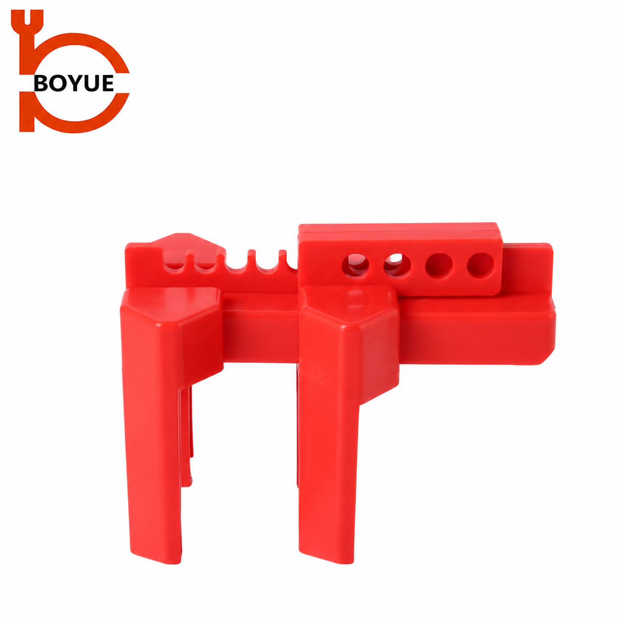
The adjustable design above illustrates another handle-restraint form. It does not show a completed installation or a verified process boundary. Do not combine adjustment details from one model with instructions for another, and do not infer that a device can hold an arbitrary valve position simply because its rail has several visible holes.
Identify where residual energy could remain
Consider the spaces inside the defined work boundary, not merely the supply line. A closed valve may leave material or pressure within a housing, branch, hose or connected section. Other hazards can include temperature, chemical exposure and mechanical movement. The responsible engineering and operations personnel should identify the actual hazards and the controls for that specific system.
Ask what the work will expose. Opening a housing, disconnecting tubing or removing an instrument can expose a different trapped volume from the volume monitored during normal operation. A pressure indication from elsewhere in the system may not represent that volume. Verification points must be selected for the work boundary, using suitable methods defined by the approved procedure.
Avoid assuming that no flow means no pressure. No visible discharge can have several explanations, including an unsuitable observation point or an obstructed path. Workers should not improvise a conclusion when the expected response is absent. The plan needs an explicit hold point and escalation route for observations that do not match the documented verification criteria.
Plan release and verification as separate decisions
The procedure should define how hazardous residual energy will be controlled and how the resulting state will be verified. Completing a release action is not the same as demonstrating that the entire work boundary has reached the required state. Identify who performs each action, what evidence is expected and who accepts an unexpected result.
CCOHS lockout guidance describes control of stored energy and verification as parts of the broader lockout process. Translate those principles into equipment-specific instructions prepared by competent personnel. A generic article cannot determine a safe discharge destination, suitable test instrument or permitted release sequence for an unidentified fluid and installation.
Do not loosen fittings, covers or other pressure-containing parts as an improvised pressure test. Use only the engineered release and verification arrangements approved for the equipment and task. If the required means is unavailable or cannot be identified, maintain the hold on work and obtain an authorized resolution rather than trying a more convenient opening.
Questions for the isolation-planning meeting
The table is a planning aid, not an operating sequence. Complete it with the actual procedure references and acceptance criteria before the job. The evidence column asks for traceable information rather than a generic statement that the valve is closed.
| Planning question | Evidence to identify | Hold point if unresolved |
|---|---|---|
| What is the work boundary? | Identified component and current line or equipment information | Do not approve work against an uncertain boundary |
| Which energy paths reach it? | All relevant feeds, bypasses and other energy sources | Reassess isolation scope before proceeding |
| What restrains the valve handle? | Exact accessory, approved position and locking arrangement | Resolve hardware fit before use |
| How is residual energy controlled? | Equipment-specific release or restraint method | Do not improvise a vent or drain |
| How is the required state verified? | Approved points, method and documented criteria | Escalate unexpected or unavailable evidence |
| Could hazardous energy return? | Assessment and required continued checks or controls | Keep work stopped if protection cannot be maintained |
| Who accepts changes? | Named responsible role and change process | Review changed conditions before resuming |
Add enough detail that a replacement planner can understand what remains open. For example, “verification point not accessible with current platform” is more useful than “check pressure.” It identifies a practical obstacle requiring a design or access decision. Avoid signing off a generic checklist while carrying its unresolved details in an informal message.
Address pressure that could return during the job
A successful initial check describes an observed condition at a point in time. The work plan must also consider whether hazardous energy could reaccumulate. Potential contributors depend on the installation and may include another connected source, a leaking isolation boundary or changing thermal conditions. Have the responsible team assess the actual mechanisms rather than copying a universal monitoring interval.
For covered work, OSHA 1910.147(d)(5) addresses stored energy and continued verification where hazardous reaccumulation is possible. The procedure must establish the controls appropriate to the task. A lockout supplier’s photograph or accessory datasheet cannot determine whether the system needs continued observation, additional isolation or another engineered arrangement.
State what happens if an indication changes or a verification result becomes uncertain. Workers need a clear stop-work and communication route. Do not treat an unexpected pressure return as a reason to tighten the handle restraint, bypass a step or continue while someone watches a gauge. Reassess the protection through the authorized equipment-specific process.
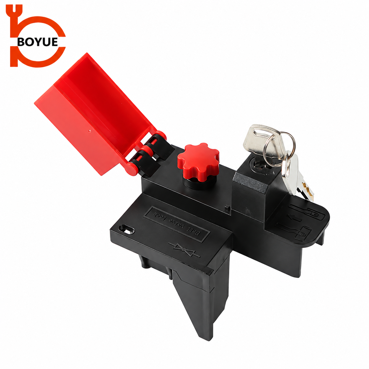
The integrated-cylinder product above has a different locking arrangement from a separate-padlock accessory. Confirm its permitted users, key ownership and removal controls. Its integrated cylinder does not provide evidence about downstream pressure, internal leakage or the suitability of the chosen isolation boundary.
Keep nearby work and other energy sources in view
Being able to reach a valve is not a replacement for the required energy-control procedure. OSHA’s interpretation concerning local isolation valves explains that proximity to the valve did not provide sufficient control in the servicing situation discussed. Do not extend the cord-and-plug exclusive-control exception to a process valve merely because the task is short.
Consider energy sources beyond the process fluid. An instrument may have an electrical connection; a pump may have electrical and mechanical hazards; a connected assembly may have stored movement or elevated temperature. Each relevant source belongs in the job assessment. Applying a ball valve accessory is not evidence that those other sources have been addressed.
For a related discussion of residual energy after disconnecting an air supply, see pneumatic lockout and stored energy. The shared principle is to verify the actual work boundary. The release and verification methods for one medium should not be copied into another process without equipment-specific review.
Prepare records that survive a change of personnel
Document the identified isolation points, required positions, lock or key references, verification method, acceptance evidence and unresolved conditions. State the limits of the work authorization so an incoming person does not interpret a narrow approval as permission to open additional equipment. Keep the record current when scope or conditions change.
For a group job, connect the pressure-verification record to the approved personal-protection arrangement. The group lockout box procedure guide explains the role of controlled keys and individual protection. Capturing keys supports control of the isolation locks; it does not replace the process assessment or verification of the equipment state.
Before the job, review an example record with operations, maintenance and the responsible coordinator. Ask whether it clearly distinguishes “handle secured,” “residual energy controlled” and “required state verified.” If the same checkbox stands for all three, revise the record so uncertainty remains visible and a partial task cannot appear complete.
Educational overview
SAFE Work Manitoba’s Lock Out Procedures video provides general context for hazardous-energy control. It is useful background for understanding why isolation involves more than attaching hardware. It does not supply the valve sequence, release method or pressure acceptance criteria for the process described in your own work permit.
Watch Lock Out Procedures by SAFE Work Manitoba.
Frequently asked questions
Does locking a ball valve prove the line is depressurized?
No. A compatible accessory restrains the operating handle. Residual energy, the actual isolation boundary and verification of the required equipment state must be addressed through the equipment-specific procedure.
Can a zero gauge reading alone authorize opening equipment?
Do not assume so. The approved verification method must address the actual work boundary, suitable indication and acceptance criteria. An uncertain, remote or unsuitable indication requires resolution before work proceeds.
Is a valve within arm’s reach exempt from lockout?
Do not treat proximity as an exemption. Apply the requirements and equipment-specific energy-control procedure relevant to the servicing task; the cord-and-plug exception cannot simply be transferred to a valve.
What should happen if pressure returns after verification?
Stop the affected work and follow the authorized escalation process. Maintain protection and reassess the source and isolation arrangements before resuming; do not improvise a release or rely on tightening the handle lockout.