Pneumatic Lockout with Multiple Air Supplies: Define the Whole Boundary
Pneumatic lockout with multiple air supplies begins by defining every connection that can deliver hazardous energy into the work area. Locking one visible hose connection does not establish that a second supply, shared branch or retained pressure has been addressed. Match the actual machine and task to a current energy-control procedure, resolve alternate paths, then select restraints for the identified interfaces. This guide focuses on supply-boundary review. It is not an instruction to disconnect pressurized hoses, operate unfamiliar valves or troubleshoot energized equipment; qualified personnel must follow the employer’s approved method.
Why the nearest hose can be misleading
The most accessible connection may be the one operators use every day, but visibility does not make it the complete supply boundary. A machine may have another connection associated with auxiliary equipment, a temporary service arrangement or an independently supplied module. These are possibilities to investigate from current drawings and field evidence, not assumptions about every pneumatic machine.
Define the maintenance task precisely. Work on an external accessory and work inside a mechanism may expose people to different hazards and require different boundaries. The responsible reviewer needs the actual work scope before deciding which sources must be controlled. Avoid approving a generic “air off” instruction for tasks whose energy paths have not been examined.
The OSHA control of hazardous energy standard explains that equipment can contain several kinds of hazardous energy. Use that broader perspective even when the job appears primarily pneumatic. Electrical control, gravity or mechanical restraint questions should be assigned to the appropriate competent personnel rather than excluded from the review.
Build a source record that follows the real equipment
Start with the current machine identifier, work scope and available drawings. List the known supply connections and the equipment or area each connection serves. Record the identifier and location of the proposed energy-isolating device for each relevant source. Keep uncertainty visible instead of turning an unverified connection into an assumed safe boundary.
Compare the documents with the installed arrangement through the site’s authorized survey process. If labels, hose routes or connection identities disagree, resolve the discrepancy before the procedure is used for the affected work. A color-coded hose can help organization, but color alone cannot establish its source, destination or isolation function.
For coupling restraint, the BOYUE AS-01 pneumatic quick-disconnect lockout is a product to assess against an identified fitting. It does not determine where the work boundary belongs. Confirm the exact interface and documented use after the source record establishes what needs securing.
Distinguish source isolation from prevention of reconnection
A fitting restraint can prevent a particular disconnected interface from being reconnected when used in its approved application. That purpose differs from controlling an upstream energy source and from dealing with pressure retained elsewhere. Document these functions separately so that a purchase description cannot become an incomplete work instruction.
The quick-disconnect selection guide covers coupling compatibility and padlock fit. Here, the prior question is whether that coupling is the relevant interface and whether other connections remain. A perfectly matched restraint on one fitting cannot compensate for an unaddressed parallel supply.
An upstream shutdown also does not, by itself, establish every downstream condition. The employer’s method must address the machine’s stored energy and verification requirements. Do not use a disconnected hose, a silent actuator or one gauge reading as a universal substitute for that method.
Review alternate paths with a practical boundary table
This table provides questions for the responsible reviewer. It describes investigation and documentation, without prescribing a universal valve sequence or declaring any specific arrangement safe. The CCOHS overview of lockout and tagout explains the importance of identifying energy sources, isolating them and verifying the result within an established procedure.
| Finding during the review | Boundary question | Evidence to retain |
|---|---|---|
| Two identified supply hoses | Can either supply affect the planned work? | Source-to-equipment record and approved control points |
| A branch serves adjacent equipment | Does shared operation affect the proposed boundary? | Current schematic and responsible review |
| A temporary connection is present | Is it included in the current procedure? | Identified connection and resolved change record |
| A separate module has its own supply | Is the module included in the task exposure? | Work-scope definition and module energy record |
| A pressure indication conflicts with expectations | Has the safe condition actually been established? | Hold and investigation under the approved procedure |
| An unknown connection cannot be traced | Can the procedure be relied on for this job? | Open discrepancy with an assigned responsible person |
Do not resolve an unknown path by experimenting with live connections. Hold the affected work and refer the issue to people authorized to determine the system arrangement. The useful output is a verified boundary record, not a plausible explanation based on hose appearance.
Match each restraint to an identified interface
Once the boundary and method are approved, prepare a device list that corresponds to the actual interfaces. Record the coupling profile, the exact locking accessory, intended personal lock and any installation limitations in the manufacturer information. Distinguish alternatives from items approved for the same location; similar purpose does not establish interchangeability.
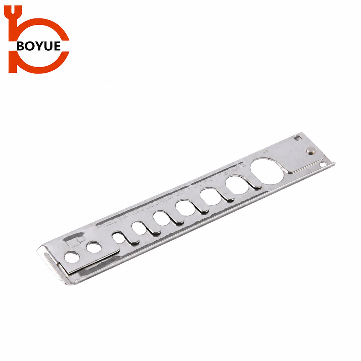
The AS-02 stainless-steel fitting-lockout illustration shows another product configuration. It is included to explain why a stores description should identify a particular accessory rather than request a generic “air lock.” Its visible openings do not provide a pressure rating, demonstrate installed fit or establish suitability for an unknown connector.
If a sample does not fit as documented, keep that result as an unresolved application issue. Do not enlarge apertures, remove retaining features or combine parts from different devices to obtain an apparent fit. Request the correct documented product or an approved alternative arrangement.
Keep personal protection clear when sources multiply
Several source points can make the protection arrangement harder to understand. The approved procedure must tell each authorized person how their protection is maintained across the defined boundary. Avoid relying on an informal statement that another worker has already “done the air.” Responsibility and verification must remain clear to the people exposed.
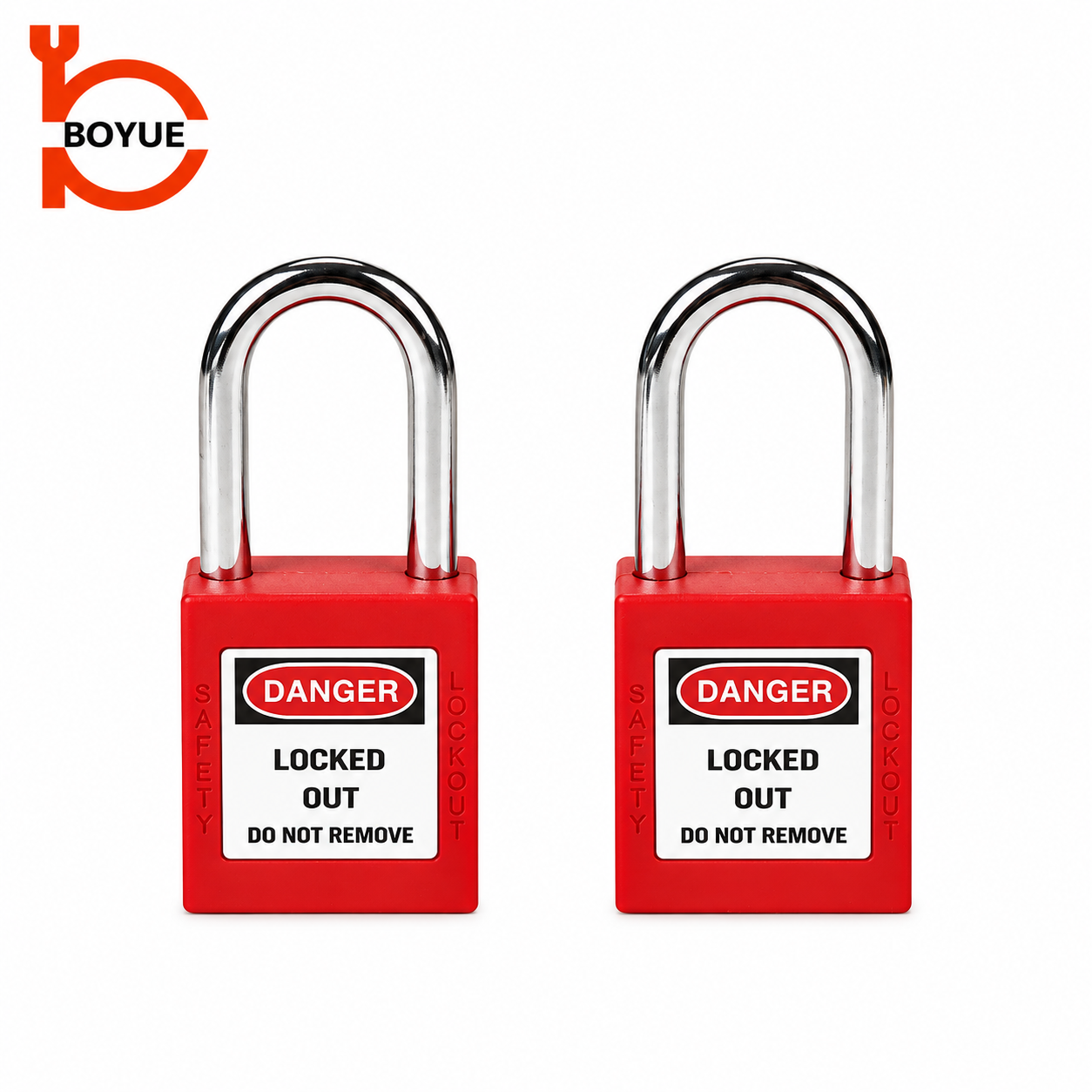
Confirm the personal lock and accessory combination together. Record which locks are assigned under the site’s key-control system, and ensure the selected shackles work with the designated locking features. A supplier demonstration using a different lock body is useful product information but does not prove the issued combination will fit.
Where a group method applies, use the established group lockout box procedure principles as supporting context. Do not invent an additional group arrangement because there are more connections than expected. Refer the changed scope for review and retain a clear connection between the isolation record and the approved group process.
Make verification specific to the task
The procedure should define how qualified personnel establish that the relevant hazardous energy is controlled before work begins. Verification must correspond to the equipment, sources and exposures involved. An action suitable for one machine may not establish the required condition on another assembly with different internal components.
Pressure can be retained or can return under conditions the reviewer must evaluate. The existing stored-energy article addresses that separate topic. Supply mapping should identify where further assessment is needed without pretending that a connector restraint vents the downstream system.
The general educational video below helps explain why shutdown, isolation and verification belong to a complete process. It does not show the AS-01 or AS-02 being installed, and it cannot replace the equipment-specific procedure or the employer’s training.

Watch Lock Out Procedures by SAFE Work Manitoba.
Control temporary supplies and later changes
A temporary arrangement deserves an explicit record because it can be removed from memory before it is removed from the machine. Identify who authorized it, which equipment it affects and what review is needed before the normal procedure is used again. Do not assume that a connection described as temporary is outside the maintenance boundary.
When equipment is moved or an auxiliary module is added, compare the new arrangement with the current source list. Purchasing another lockout device alone does not close the change. The document, field identifiers, device list and worker understanding must still agree.
At handover, give the next responsible person the current boundary and the status of unresolved findings. A useful record distinguishes a confirmed source, an excluded source with a documented reason, and an unknown connection requiring investigation. That distinction prevents a partially completed survey from being reused as an approved procedure.
Ask suppliers for precise product information
A useful inquiry identifies the proposed coupling, actual measurements and the desired restraint function. Include photographs that show the interface clearly, while keeping confidential process details out of unnecessary correspondence. Ask for the exact accessory variant and its current instructions rather than requesting a general promise that a product fits “all air lines.”
Retain the supplier’s answer with the application assessment. The supplier can clarify product geometry and intended use; the employer must decide whether the complete method protects the task. Mark any unconfirmed alternative as pending so that receiving or stores staff cannot issue it as an equivalent replacement.
Frequently asked questions
Does locking the main air connection cover every other supply?
Only an equipment-specific review can establish the relevant boundary. Identify alternate and shared paths and determine whether they can affect the task. The nearest or largest connection is not automatically the only source requiring control.
Does a quick-disconnect lockout remove trapped pressure?
A fitting restraint should not be treated as a pressure-release device. Its documented role and the machine’s stored-energy controls are separate matters. Use the approved procedure to establish and verify the required condition before work.
Can an unidentified spare hose be ignored?
Do not assume an unknown connection is harmless. Hold the affected work while authorized personnel determine its source, destination and relevance. Record the resolution so that the next survey does not repeat the same uncertainty.
What should be recorded when two devices look interchangeable?
Record the actual model, interface, supplied instructions and approved application decision for each. Appearance and a similar product name do not establish equivalent fit or function. Keep unapproved substitutes outside available application stock.