Ball Valve Lockout Device: Selection and Handle-Fit Checks
A ball valve lockout device should be selected for the actual valve handle, the position that must be secured, the available installation space, and the intended personal lock. A nominal pipe-size range is only an initial screening aid. The device must engage the lever or other specified handle feature in the manufacturer’s approved configuration without altering the lockout or the valve. Before purchasing, confirm the exact model, handle geometry, retaining arrangement, and sample fit. This guide compares the decisions behind common designs and explains what to include in a useful inquiry.
The separate process-isolation decision remains with the site’s approved procedure. Restricting a handle’s movement does not establish that the valve is leak-tight, that pressure is absent, or that the work area is safe to enter.
Start with the valve position and handle design
Identify the asset and the valve that the isolation plan actually names. Confirm the required position before considering hardware. A quarter-turn lever, a T-handle, an actuator, and a handwheel present different interfaces; a device intended for one should not be assumed suitable for another.
Do not operate a process valve merely to see whether a lockout fits. Have authorized personnel establish the conditions under which a sample may be evaluated. The purchasing record should describe the approved position and handle configuration, including whether a handle has been replaced, shortened, bent, or covered by an accessory.
Handle orientation is useful identification information, but it is not proof of the internal valve condition. An approved isolation assessment must address the process, valve arrangement, retained energy, and verification requirements. HSE’s safe isolation of plant and equipment guidance is useful background on that wider assessment, especially for intrusive process work.
Compare designs by how they retain the handle
Catalogue names such as standard, adjustable, and universal describe broad product families. They do not replace a drawing or approved fitting instructions. The practical comparison is how a particular design captures the handle and what prevents the handle and device from moving together.
| Design to evaluate | Compatibility question | Information to request |
|---|---|---|
| Formed metal lever lockout | Does the approved retaining geometry suit this lever and surrounding valve assembly? | Exact model, applicable size definition, handle-clearance limits, and permitted lock positions |
| Adjustable molded lever lockout | Can the adjustment engage this handle securely without reaching an unsuitable end position? | Adjustment instructions, permitted settings, clearance requirements, and a representative fit check |
| Device with an integrated key cylinder | Do its physical fit and built-in key-control arrangement meet the site’s approved program? | Fitting instructions, supplied keying option, ownership rules, and removal procedure |
| Special handle or obstructed installation | Is there an approved configuration for the actual interface? | A reviewed alternative rather than an improvised adaptation of a standard model |
Boyue’s formed steel ball valve lockouts are one product family to evaluate. Confirm what the published range measures and how the intended variant is fitted. A small product photograph cannot establish compatibility with a valve that the supplier has not identified.
Prepare a handle and clearance survey
Identify the actual lever profile
Record the lever length, width, thickness, shape, and relevant projections. Include a grip sleeve, bent end, mounting nut, or other feature if it affects engagement. Do not submit measurements from an uncovered replacement lever when the installed handle has a different profile.
Supply clear photographs of the handle and the retaining area from safe, accessible viewpoints. Keep the asset identifier associated with the photographs so similar valves are not confused. If a supplier asks for an additional dimension, identify the measurement points rather than guessing from a perspective photograph.
Show the surrounding obstruction envelope
Nearby pipework, insulation, brackets, walls, and neighboring valve handles can limit access. A device may fit a loose sample but be impossible to position on the installed valve. Show the area into which the device, padlock, and tag must extend.
Consider the space needed to inspect engagement as well as the space needed to attach the device. A configuration that hides the locking interface behind a fixed obstruction can be difficult to check consistently. Ask whether an approved different model or arrangement would give better access.
Provide the intended padlock details
For a design that requires a separate padlock, identify the actual lock model, shackle diameter, usable length, and lock-body envelope. Check that the lock can close fully through the permitted features without interference. Multiple visible holes do not automatically establish how many workers a configuration can protect.
Physical lock fit and key ownership are separate decisions. The safety padlock keying systems guide explains the access relationships to settle when issuing personal locks or defined lock sets.
When does an adjustable model make sense?
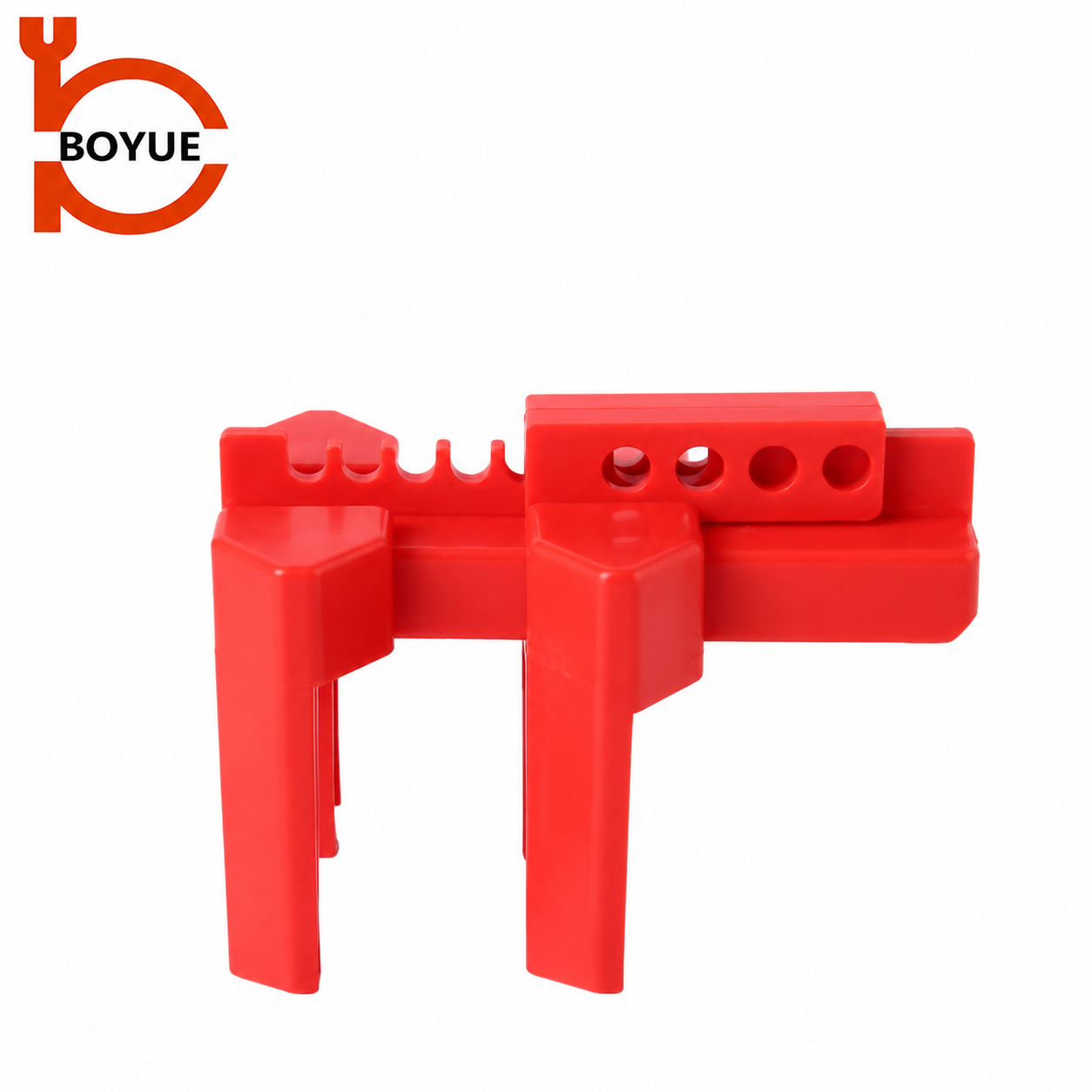
An adjustable design may reduce the number of variants needed for an approved group of handles. That benefit should be demonstrated with the actual handle profiles rather than inferred from a wide catalogue range. Different width, thickness, and obstruction conditions can still require different solutions.
The Boyue ASBV-01/ALBV-01 adjustable ball valve lockout page provides a relevant family for that discussion. Request the instructions for the supplied variant and confirmation of the intended adjustment and locking positions. Do not carry a specification from the smaller variant into an order for the larger one without checking it.
If an adjustment only appears to work when a component is bent, trimmed, or pressed beyond its intended travel, treat that as a problem to resolve. An adjustable product is not permission to modify its structure. A larger nominal range is also not automatically a better choice if the retaining arrangement is unsuitable for the handle.
Integrated key cylinders need a separate ownership decision
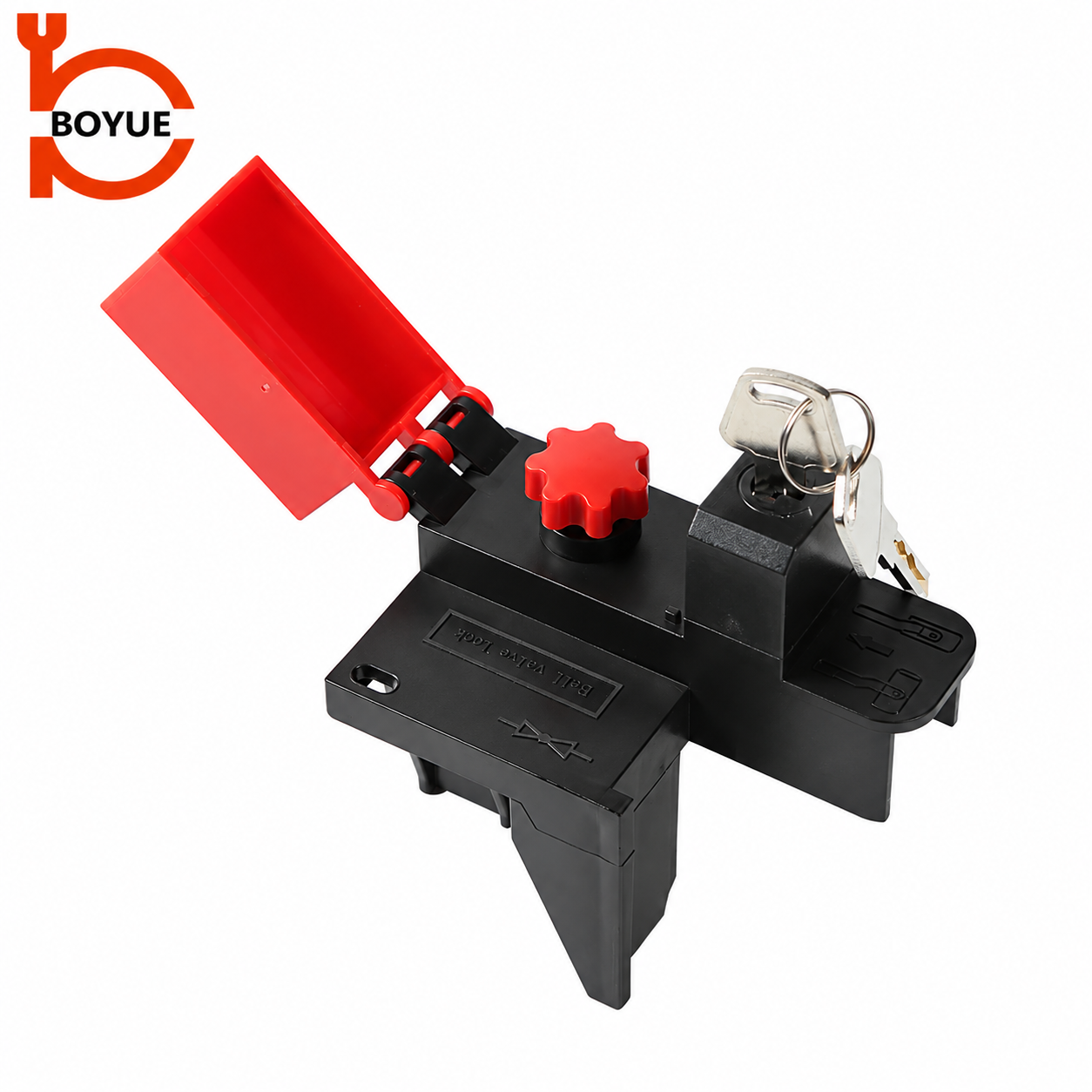
Some devices use a built-in lock cylinder instead of a separate padlock. Boyue lists this approach on the BYFM13 ball valve lockout product page. Confirm the exact physical variant and keying configuration in the quotation.
The relevant question is not simply whether the device can be locked. Decide who owns the key, who is protected by the arrangement, and how participation and removal are controlled. A key shared for convenience may create access rights that the site has not approved.
Where several people work under a coordinated arrangement, the site must define the complete method. The group lockout box guide discusses key-control responsibilities for that distinct method. Neither a photograph of an integrated cylinder nor a general group-lockout article establishes approval for a particular valve task.
A practical sample evaluation
Agree an evaluation method before accepting a substitute model. Use a safe representative arrangement with no live process depending on the sample result. Have the proposed device, correct handle or representative fitting assembly, intended personal lock where applicable, and current instructions available together.
| Evaluation item | What to check | Reason to hold acceptance |
|---|---|---|
| Model identity | Delivered variant matches the reviewed product and instructions | Unclear model, changed geometry, or an undocumented substitution |
| Handle engagement | All intended retaining features engage in the approved position | Partial engagement, forced installation, or a requirement to modify parts |
| Locking interface | The intended lock or integrated cylinder secures the approved configuration | Incomplete closure or access inconsistent with the site’s protection method |
| Access and identification | Engagement can be inspected and identification remains usable | Obstructed inspection, interference, or unreadable identification |
| Condition | No relevant cracking, distortion, damaged openings, or missing parts | Damage that affects the retaining or locking function |
This is a purchasing checklist, not a certification test or an instruction to apply force to a live valve. Record what the sample evaluation actually covered. Do not describe a brief desk review as proof of pressure isolation, a universal fit, or resistance to every removal method.
Keep handle restraint separate from process safety
A lockout device normally addresses an unauthorized change of the selected control or valve position. It does not repair a damaged valve seat, remove a hazardous substance, or control pressure entering through another route. The work’s isolation boundary and verification method must be established separately.
The CCOHS lockout guidance explains why hazardous and residual energy belong in the wider procedure. Its educational guidance should be applied alongside the rules and equipment-specific requirements relevant to the site.
A handwheel cover is a different interface from a lever lockout. If the asset has a wheel, use the separate gate valve lockout sizing guide as a measurement starting point rather than transferring its wheel-diameter table to a ball-valve lever.
What makes an inquiry ready for a useful response?
Include the asset reference, required position, handle measurements, safe-access photographs, surrounding clearance, intended lock model or integrated-key requirement, quantities, environment, and identification needs. Ask the supplier to distinguish confirmed data from assumptions that still require a sample.
Keep the accepted model and configuration in the asset record. A later valve replacement, altered handle, or different padlock can change compatibility even when the purchase description remains the same. For a broader application discussion, see Boyue’s industrial lockout applications.
Further learning
Lock Out Procedures from SAFE Work Manitoba provides educational background on energy control. It does not demonstrate a fit test of these Boyue products or approve a process-isolation arrangement. Follow the applicable site procedure and manufacturer instructions for the work.
Watch Lock Out Procedures by SAFE Work Manitoba on YouTube.
Frequently asked questions
Can I select a ball valve lockout from nominal pipe size alone?
No. Confirm the actual handle profile, required position, retaining arrangement, surrounding clearance, and intended lock. Clarify what the supplier’s stated size range measures.
Does an adjustable device fit every handle within its advertised range?
Do not assume that it does. Handle thickness, shape, obstructions, and permitted adjustment positions can still affect compatibility. Review the exact configuration and a representative sample.
Does an integrated key cylinder replace the need for ownership rules?
No. The site still needs an approved key-control, participation, and removal arrangement. Physical locking capability does not determine who is authorized to release protection.
Does locking the lever prove that the valve is leak-tight?
No. Handle restraint does not verify valve integrity, absence of pressure, or the adequacy of the isolation boundary. Those conditions require the approved assessment and verification method.