
Clamp On Circuit Breaker Lockout: Verify Fit Before Ordering
A clamp on circuit breaker lockout must grip the actual breaker handle, remain captive after a personal padlock is fitted, and fit within the available panel space. Choose it by handle geometry and the exact device instructions, rather than voltage labels alone. For procurement, collect the breaker model, photographs, handle measurements and padlock dimensions, then approve a sample on the intended equipment. A clamp that appears tight is only one part of the assessment: the energy-isolating device, stored energy controls and verification method still belong in the equipment-specific procedure.
This guide addresses clamp-on device fit and purchasing acceptance. For pin-style devices and small DIN-rail breakers, use the separate miniature circuit breaker lockout guide. Do not assume those mechanisms or fitting instructions transfer to a larger clamp-on model.
Start with the breaker and the task
Record the manufacturer’s full breaker reference, including the handle arrangement and installed accessories. Two breakers in the same electrical rating family can have different toggles, recesses and linked handles. An accessory that works on one unit may obstruct an adjacent switch or fail to grip another. A photograph should show the complete front, the handle profile and the surrounding cover, with the equipment safely accessible under the site’s rules.
Have the responsible qualified person establish whether this breaker is an appropriate isolation point for the work. Circuit identification, multiple supplies and electrical testing cannot be resolved by buying a clamp. A handle in an OFF position does not prove that every part of the enclosure is de-energized. This article does not authorize opening a panel, approaching exposed conductors or conducting energized fitting trials.
OSHA’s electrical work-practice requirements address disconnection, locking and tagging, and verification for electrical work within their scope. Apply the correct jurisdiction and task-specific requirements; a product description does not establish that an installation meets them.
Measure the surfaces that actually engage
A useful drawing identifies handle width, thickness, exposed projection and the available seating surface. Show the dimensions at the place where the selected clamp engages, rather than measuring the broadest decorative face. If the handle slopes or has a lip, capture its profile. Those details influence whether the clamp stays seated as the handle resists movement.
Also record the position of the breaker face around the handle. Some clamp designs use a cleat or support feature that must engage a suitable recess. Others use a different restraint mechanism. Confirm the exact model’s supplied parts and assembly instructions. Never add improvised packing, adhesive or a substitute screw to compensate for a mismatched clamp.
Allow for measurement uncertainty. A nominal maximum dimension is a screening limit, not a guarantee that any shape below it will fit. If a handle is near a listed limit, submit the actual profile and request a fitting review. Record dimensions in one unit system or show clearly labelled conversions, avoiding a mixture of millimetres and unlabelled inch fractions.
Compare candidate devices systematically
The following table is a purchasing and sample-review checklist, rather than a certified compatibility chart. Its acceptance points must be resolved against the exact breaker and device instructions.
| Check | Information to collect | Reason to withhold approval |
|---|---|---|
| Handle engagement | Width, thickness, profile and contact surfaces | Clamp sits on an edge or moves off the handle |
| Clamp adjustment | Exact screw and cover arrangement | Tightening requires improvised tools or damages the handle |
| Support parts | Supplied cleat and approved position, where applicable | Support cannot seat as specified |
| Padlock fit | Shackle diameter, usable opening and body size | Shackle fits the hole but body prevents full closure |
| Panel clearance | Installed depth, adjacent switches and cover movement | Cover presses on lock or neighboring circuits are obstructed |
| Final restraint | Approved fitting check with the actual lock installed | Clamp can be removed or safe position is not maintained |
The programme basis is explained in CCOHS’s lockout guidance. This table adds practical purchasing questions; it does not reproduce a statutory test method or prescribe a universal pulling force.
What the BOYUE clamp-on range establishes
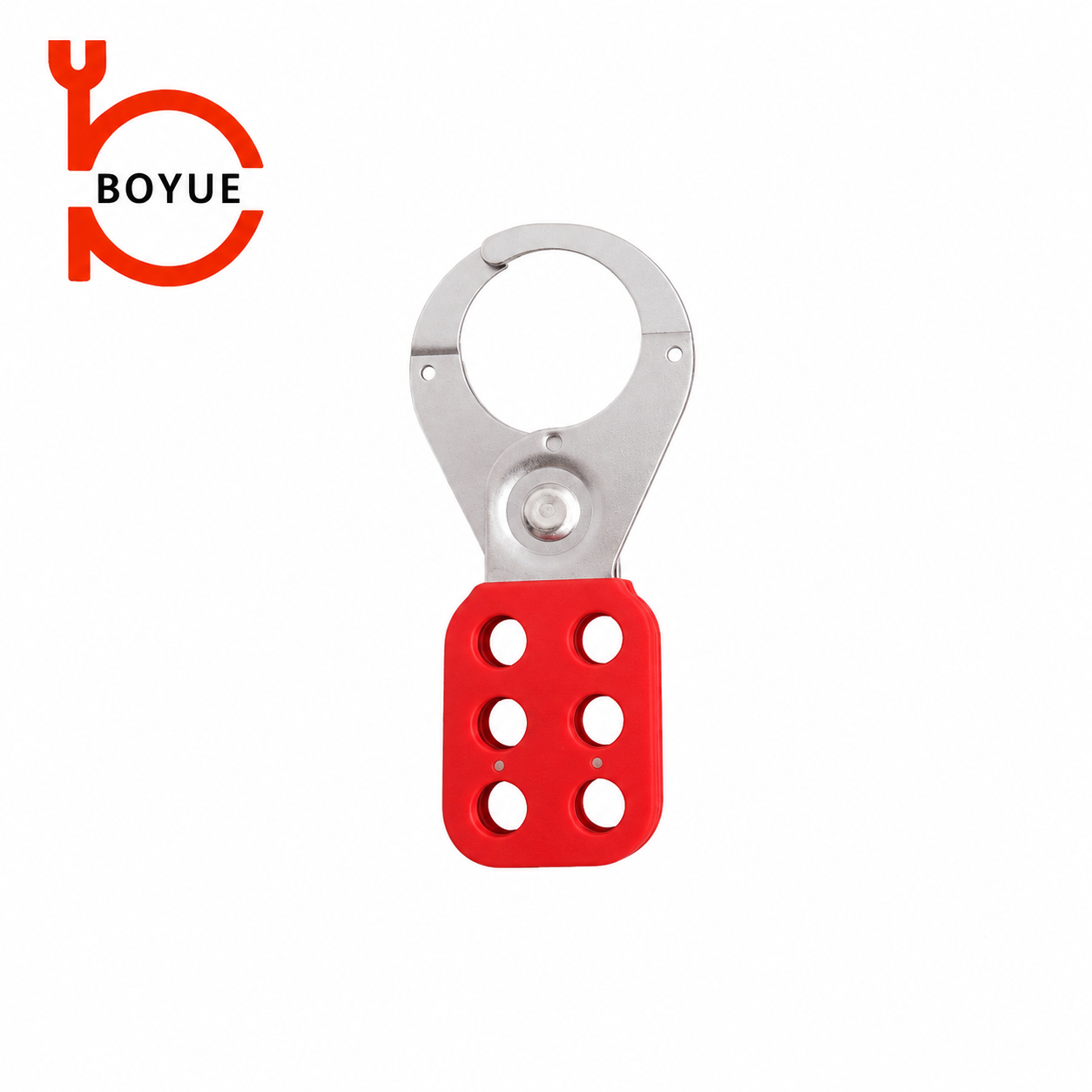
The BOYUE CB-07, CB-08 and CB-09 product page identifies a clamp-on family. Treat the pictured device as a reference for that family, then confirm the exact variant on the quotation. A shared catalogue page is not evidence that the variants have identical handle capacities or supplied accessories.
Request a current fitting drawing and instructions for the model being offered. Match those documents to the sample’s adjustment mechanism and packaging reference. If a distributor changes the proposed variant, repeat the compatibility review before accepting a bulk substitution. Avoid translating a competitor’s voltage or dimensional chart into a BOYUE compatibility claim.
The isolated product illustration shows the adjustment mechanism clearly, but it is not an installed demonstration. The receiving record should identify the actual breaker tested and the approved lock. A generic statement such as “fits our panels” is difficult to apply later when a panel is replaced or its handle arrangement changes.
Include the personal padlock in the fitting trial
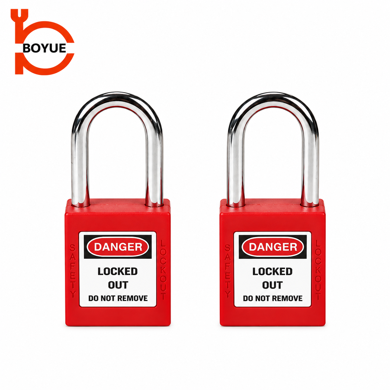
Shackle diameter alone is insufficient. Check usable shackle height, internal width and the space occupied by the lock body. The padlock must close fully without forcing the clamp out of its intended position. It must also prevent access to any release feature that the device instructions require it to secure.
Use the site’s approved personal lock during the review. An unusually thin sample shackle can create a misleading result if production workers carry larger locks. Conversely, changing a lock to obtain clearance can introduce an unapproved keying or identification arrangement. See safety padlock keying systems for those separate management decisions.
For several people, do not assume that stacking locks or adding a hasp is acceptable. Check whether the exact accessory combination is approved and whether it still fits the panel. If the site uses group isolation, refer to the established group lockout box procedure rather than treating an improvised chain of accessories as a group system.
Check clearance with the assembly complete
A device can fit an exposed toggle yet fail after the panel cover, lock body and identification tag are considered together. The responsible person should review the complete installed assembly under safe conditions. Check normal access routes and the possibility of another switch or enclosure door contacting the clamp. Do not require a worker to remove the lock simply to close a cover.
Consider nearby breakers individually. A broad lock body might obstruct identification or operation of a neighboring circuit that needs to remain available. That is a layout issue to resolve during approval, rather than an instruction to move or alter electrical equipment. Preserve the panel manufacturer’s required access and enclosure arrangements.
Document any installation-specific limit. Approval might apply to one breaker model in one enclosure position with one lock model. State those boundaries directly. A photograph and a reference number can make the approved arrangement easier to reproduce, while a written exception prevents the same clamp being casually issued for a different toggle.
Separate mechanical fit from energy verification
A fitting check asks whether the clamp and lock hold the selected isolating device as intended. Energy verification asks whether hazardous energy relevant to the work has actually been controlled. Passing the first question does not answer the second. Electrical testing must follow the site’s approved method and be performed by the appropriately qualified person with suitable equipment.
Other energy sources may remain even after the electrical supply is disconnected. A motor-driven machine can include stored pressure, elevated parts or rotating assemblies. The procedure must identify and address those hazards. NIOSH’s hazardous energy control overview explains why a complete written programme matters beyond the choice of hardware.
The SAFE Work Manitoba video below provides general lockout education, including the distinction between hardware and an organized procedure. It is not a fitting guide for CB-07, CB-08 or CB-09, and its examples do not replace the current local requirements.
Watch Lock Out Procedures by SAFE Work Manitoba.
Receive and control approved stock
At receipt, compare the model, mechanism and supplied accessories with the approved sample. Check for cracked bodies, damaged threads, missing parts and unclear instructions. Hold any changed item for review, even if its colour and packaging look familiar. Retain the supplier reference so a later replacement order can be checked against the same configuration.
Record which breaker applications are approved and which remain unresolved. Store rejected or unassessed devices separately from serviceable stock. A device should not enter a general kit merely because it was purchased. If repeated fitting problems arise, revisit the application list and sample selection rather than encouraging workers to tighten harder.
Frequently asked questions
Does the voltage printed on a clamp prove compatibility?
No. Voltage categories can help organize a catalogue, but the actual handle shape, engagement mechanism, panel clearance and approved application determine whether a particular assembly fits.
Can one clamp be approved for every breaker in a building?
Only if every relevant application has been assessed and documented within the device instructions. A successful trial on one model does not establish compatibility with other handles or panels.
Should a loose clamp be secured with tape?
No. Withhold approval and investigate the model, fitting method and condition. Tape or improvised packing is not a substitute for the device’s specified restraint mechanism.
What should an enquiry include?
Send the breaker reference, safe photographs, handle profile and measurements, enclosure constraints, proposed padlock dimensions, required quantities and the exact installation contexts needing approval.