
Cable Lockout Routing: Check Slack, Anchors and Restraint
Cable lockout routing should prevent every included energy-isolating device from leaving its required safe position. Check the actual route, its fixed reaction points, movement available at each handle, and whether slack can migrate from one span to another. A cable that looks tight near the lock body may still permit movement elsewhere. Use the exact device instructions and the employer’s equipment-specific procedure; reject an uncertain route before anyone enters the danger area. This guide explains how to review a proposed routing arrangement, document its limits and recognize when separate devices are a better choice.
Define the route before threading the cable
Start with the machine identity and the servicing task. A cable route is meaningful only when it corresponds to the isolation points required for that task. Two valves beside each other may serve different systems; one machine may also have a distant disconnect that is easy to overlook. Copy the isolation-point identifiers from the approved procedure into a route sketch rather than choosing points because they are convenient to connect.
The CCOHS lockout guide distinguishes energy isolation from ordinary operating controls. Securing a push button or a control-panel handle is not automatically equivalent to securing the actual energy-isolating device. Establish what each component does before deciding whether a cable is an appropriate restraint.
For a proposed arrangement, identify the first point, each intermediate point, the return path and the lock body location. Mark which parts are stationary and which could move. An annotated photograph can support this record, but a photograph alone cannot show hidden travel, internal valve condition or the complete energy boundary. Any uncertainty belongs in the review, not in an improvised adjustment during maintenance.
Evaluate the reaction point, not just the loop
A restraint needs a geometry that opposes the movement you intend to prevent. A loop around two movable handles may allow both to move together. A cable passing through a removable component may remain intact while that component comes away. A smooth feature may allow a loop to slide toward an end and escape. These are routing questions even when the cable and its locking body are undamaged.
Use only attachment features and configurations permitted by the equipment and lockout-device instructions. Do not drill handles, modify a disconnect enclosure or substitute pipework as an anchor merely because the cable reaches it. Changes to an energy-isolating device require appropriate engineering and procedural review. An attachment point must also remain part of the intended boundary throughout the servicing task.
Consider the task’s disassembly sequence. A guard, cover or bracket that will be removed later should not quietly become the route’s only stationary reference. If the planned repair changes the supporting geometry, the responsible person must resolve that issue before approving the arrangement. The correct solution may involve different hardware or independently secured isolation points.
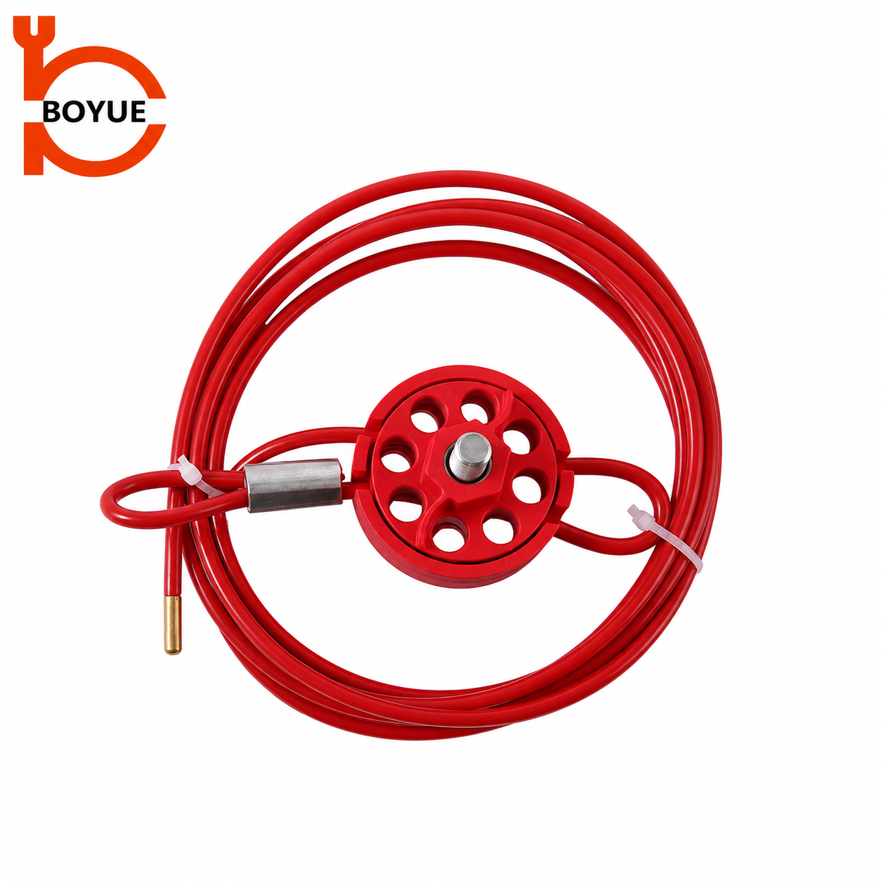
The round AC-03 family illustrates a different locking-body layout from the squeeze-handle AC-02. Body shape does not establish interchangeable routing or operating instructions. Review the supplied variant and its current instructions independently.
Check local movement and transferred slack
Inspect the entire route after the prescribed closure and locking steps. Follow the cable continuously so that a hidden loose span does not escape attention. Evaluate movement at every included isolation point using the approved, safe verification method. Do not conduct an improvised live test, force a handle or expose workers to hazardous motion to find out whether the cable will hold.
Slack can collect near bends, behind nearby components or between connected points. The span nearest the locking body may appear taut while a longer section contains enough movement to alter a handle position. Review whether normal contact, a change in cable position or movement at another point could redistribute that slack. A route should not depend on someone leaving a loose coil in one precise place.
There is no universal acceptable slack measurement for all cable lockouts and all handles. The relevant outcome is secure restraint in the required position, within the approved application. Do not invent a tension value or a maximum movement angle from a product photograph. If a repeatable assessment cannot demonstrate the required restraint, stop and choose a more suitable arrangement.
Record where movement was assessed and what method was authorized. “Cable tight” is too vague to explain why each point was acceptable. A more useful record identifies the point, its required position, the permitted attachment feature and any limitation that would require the route to be reviewed again.
Use a route review table
The table below is a planning aid, not a replacement for the equipment-specific isolation procedure. Its distinction between mechanical restraint and energy verification follows the scope of the NIOSH hazardous energy control resource: hazardous energy can include mechanical, hydraulic, pneumatic, chemical and thermal sources as well as electricity.
| Review item | Question to resolve | Reason to stop and revise |
|---|---|---|
| Point identity | Does the identifier match the approved task boundary? | An unlisted or ambiguous handle is included instead of the specified isolator |
| Reaction geometry | What prevents each moving part from leaving its safe position? | Connected parts can move together, or the loop can slip off |
| Cable spans | Can movement or contact transfer slack between points? | A remote span permits an isolator to move despite a tight-looking lock body |
| Contact surfaces | Is the route permitted at bends, edges and moving components? | The cable bears against an unsuitable edge or a component removed during work |
| Lock-body access | Can the specified locks be fitted and identified without unsafe reach? | Installation or inspection requires entering an unprotected danger area |
| Verification | How will the separate energy-isolation checks be completed? | The proposed acceptance relies only on the appearance of the cable |
Keep the completed record with the controlled procedure or its approved supporting documentation. If the route is temporary, give it a clear scope and review owner so that it does not become a permanent, undocumented standard through repetition.
Keep the cable away from avoidable exposure
Review the route for abrasion, pinch points, heat, chemicals and interference with access. Do not assume a coloured outer coating makes a metal cable electrically insulating. Likewise, a cable’s flexibility does not establish suitability for a sharp edge or repeated bending at an unidentified radius. Environmental suitability and bend limits must come from the exact product documentation.
Look beyond the installation moment. A panel door may swing, a maintenance cart may pass nearby, or a removed component may expose a new contact edge. Cable tails should be managed using an approved arrangement that preserves the lockout function and avoids tripping or snagging. Never shorten, splice or repair a cable in the field unless the manufacturer expressly provides an approved method for that model.
Keep labels and personal-lock identification visible. A mechanically successful route can still be difficult to administer if the locking body is hidden behind pipework or the attached locks cannot be read. Accessibility should support safe inspection and authorized removal without encouraging someone to bypass another person’s protection.
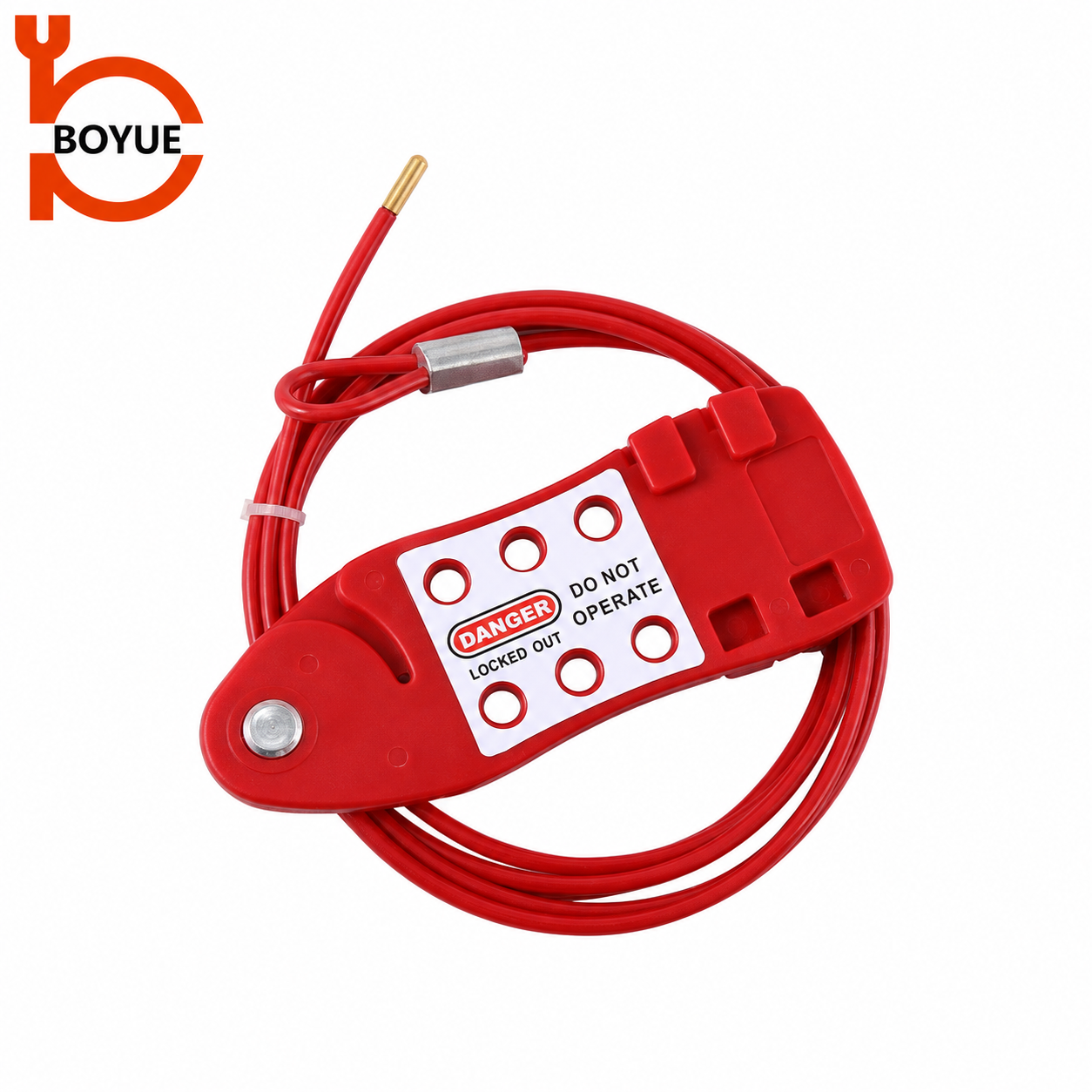
The fish-type AC-04 has a visibly different locking section. The image identifies the product family only; it does not demonstrate a route on operating equipment or establish the usable number of workers in a particular application.
Decide when to separate the isolation points
A shared cable is not automatically the simplest overall solution. Separate lockout devices may provide clearer point identification, easier access or a less ambiguous restraint. Consider separation when the proposed route crosses walkways, links unrelated systems, changes when components are removed, or makes one point difficult to inspect.
Also consider task independence. If one maintenance team finishes before another, an arrangement joining their points may create unnecessary coordination problems. The employer’s procedure must define the protection and authorized removal arrangements. Do not plan to loosen a shared cable while workers remain exposed, or assume one person’s lock represents everyone without an approved group system.
For the broader control arrangement, consult the existing group lockout box procedure. That article addresses key control and personal protection; it does not approve a specific cable route. A shared physical restraint and a group protection system answer related but different questions.
Separate fit review from condition inspection
An intact device can be routed badly, and a well-planned route can fail when worn hardware is substituted. Both checks matter. Before issue, apply the site’s pre-use condition checks to the cable, termination, body, closure and supplied locks. Remove uncertain equipment from available stock rather than trying to compensate with extra wraps.
Use the dedicated cable lockout inspection guide for condition and quarantine decisions. If the device family itself is not yet selected, the cable lockout selection guide covers the earlier purchasing decision. This routing review begins after those basic suitability questions have been resolved.
BOYUE’s AC-02 adjustable cable lockout is one product reference for discussing the required configuration. Supply the machine identifiers, permitted attachment features, route sketch, environment and personal-lock arrangement when requesting a review. Ask for confirmation against the exact supplied variant rather than relying on a generic statement that the cable is adjustable.
Validate the arrangement before routine use
Have authorized personnel review the proposed route within the employer’s controlled planning process. Compare the drawing with the actual installation, verify that all listed points are included and resolve any difference before release. An illustrative hypothetical example is two adjacent isolators that can each move when slack shifts between them: adding another wrap may obscure the issue, whereas independently approved restraints can make each point’s protection clearer.
Record the accepted configuration and the changes that invalidate it. Replacement handles, altered guarding, relocated isolators, new cable variants or a different servicing scope can all require another review. A historic photograph should not overrule a changed machine.
Mechanical route acceptance is only one part of the job. Shutdown, energy isolation, stored-energy control and verification remain governed by the approved procedure. A tight cable does not prove absence of voltage, pressure or hazardous stored movement. Begin servicing only when the full required protection has been established and verified.
Educational context: the complete lockout process
The following SAFE Work Manitoba video introduces the broader lockout process. Use it for general awareness alongside local training; it does not provide BOYUE model instructions or validate a proposed route.

Watch Lock Out Procedures by SAFE Work Manitoba.
Frequently asked questions
Can one cable secure several isolation points?
Possibly, where the exact device application and equipment-specific procedure allow it and every point remains securely restrained. Physical proximity and sufficient cable length do not prove that a shared route is suitable.
How tight should a cable lockout be?
Follow the supplied model instructions and the approved restraint assessment. There is no universal tension or slack limit applicable to every cable body, attachment feature and handle geometry.
Is a coated steel cable safe around electrical equipment?
Do not infer electrical insulation from its coating or colour. Electrical suitability must be documented for the actual product and application, with the required electrical safety measures established separately.
What if a handle can move after the cable is locked?
Do not authorize servicing on the basis of that arrangement. Keep people protected, report the failed restraint and have the responsible person revise the route or hardware under the site procedure before work begins.